


C-CAT Compressor – Cold Air Turbine Performance Analysis System
- M. Shohat, I. Ziskind, N. Sabag , E. Gildish, A. Patish, S. Sandomirsky
- Prof. Yeshayahou Levy
Today one of the most interesting and constantly developing fields of turbo-machinery is micro-jets. In spite of the micro size industrial projects usually last years and require a large team of experienced engineers. The main purpose of this project is reaching the stage of static laboratory experiment to measure the performance of a commercial compressor during a period of one academic year.
The only initial conditions of the project were dictated by a centrifugal compressor T3 “50”, which is a part of Garrett’s turbocharger used in modern cars. The rest of the parts, which included a subsonic axial turbine, centrifugal diffuser and the surrounding system, had to be designed from scratch. A measure of the projects success was the ability of a turbine to drive the compressor and the quality of the compressor-turbine operation relative to design.
The analysis system is designed to measure the performance of the compressor and as such does not require a combustion chamber. Simplicity achieved by the lack of combustion chamber however, introduces a major design problem – conventional implementation, where air leaving the compressor drives the turbine, will fail out of energy considerations. Solution of the above problem lies in a separation of air sources of the compressor and the turbine. The system will consist of a compressor pressing atmospheric air and a turbine driven by stream originating in compressed air storage tank. Altering the air flow or pressure at the turbine entrance will change the power generated by the turbine, thus allowing testing of the systems various work points.
The above describes the main principle behind a cold air turbine driven compressor and presents the ideological basis of the project.
The System
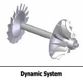
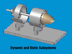
The performance analysis system is divided into three major subsystems: the dynamic system, the static system and the auxiliary system.
The dynamic system consists of an impeller, main axis and turbine’s rotor. This rotates around the main axis at a speed ranging from 56,000 to 108,000 RPM, with the axis fixed by two ball bearings.
The static subsystem, as its name suggests, includes the non moving parts of the system. They consist of aerodynamically vital parts (diffuser, turbine’s stator, nozzles and volutes); and mechanically vital parts (bearing holders and supporting legs).
The auxiliary subsystem consists of equipment vital for the experiment itself (compressed air storage tank, pipes, flow meters and thermometers).
Manufacture
The final stage of the system construction is the manufacturing stage. Apart from machining this stage involves various administrative and design tasks, among them are: searching for a manufacturing place, calculating tolerances and assembling the system. Due to lack of time only the manufacturing stage was reached, and no experiment was performed. All the major parts apart from the volutes were manufactured; dynamic system was connected using pressure fit and assembled with the static system.
