Facilities

Facilities

Our lab is equipped with a diverse range of state-of-the-art facilities and advanced equipment, including high-speed imaging systems, laser diagnostics, and specialized combustion labs. These facilities enable us to conduct detailed experiments, analyze combustion processes, and develop innovative diagnostic techniques. With our world-class infrastructure, we are committed to providing a conducive environment for groundbreaking research and driving advancements in the field of aerospace combustion.

Laboratory Infrastructure
Air compressor:
+
  • Mass flow rate: 0.25 kg/s
  • Pressure: 13 bar
  • Control: Mass flow controllers
Gas delivery
+
  • Air
  • N2
  • O2
  • Ar
  • He
  • CH4
  • H2
  • NH3
Ventilation
+
  • Overhead hoods (4): 800 m3/min
  • Chemical hood
Diagnostics
GC-MS
+
  • Thermo Scientific Trace 1300 GC
  • PIONA Analysis
  • H2 – C15 capability
  • Gas or liquid injection
High-Speed Infrared Imaging
+
  • Telops FAST M3k
  • Spectral range: 1.5 – 5.4 μm
  • Resolution: 320 x 256 pixels
  • Frame rate: 3,100 fps (full res) – 100,000 fps (64 x 4 pixels)
  • Exposure time: 1 μs – full frame
Hyperspectral Infrared Imaging
+
  • Telops Hyper-Cam MWE FAST
  • Spectral range: 1.5 – 5.4 μm
  • Spectral resolution: 0.25 – 150 cm-1
  • Spatial resolution: 320 x 256 pixels
  • Frame rate: 0.032 – 32 cubes/s
  • Exposure time: 1 μs – full frame
Tunable diode lasers/detectors
+
  • Four mid-IR units (4 – 6 μm)
  • H2O, CO2, NO, CH2O detections
  • < 50 mW power
  • < 10,000 Hz scan rate
High-speed imaging
+
  • Photron SA-Z
  • Monochrome
  • Resolution: 1024 x 1024 pixels
  • Frame rate: 20,000 fps (full res) – 2,100,000 fps (128 x 8 pixels)
  • Exposure time: 15
Experiments
Continuous Flow Ignition Wind Tunnel
+

Continuous Flow Wind Tunnel and Flow Characteristics:

  • Stainless steel wind tunnel with a cross-section of 5 x 5 cm. Equipped with two sets of Sapphire windows allowing for detailed observation of the ignition kernel.
  • Two Mass Flow Controllers (MFC, Bronkhorst F-106BI-RGD-03-V) allow measurements and control over air flow rates of up to 15000 slpm total, and third MFC (Bronkhorst, F-203AV-1M0-RGD-55-V) allows measurements and control over fuel flow rates of 1000 slpm.
  • Two electrical resistance heaters (Tutco F077085, 36 kW) allow the flow’s temperature to reach up to 900C under heated flow conditions.
  • Fiberglass insulation on the tunnel allows to heat up the tunnel’s structure and maintain its temperature at levels similar to core flow temperature (for the preheated flow condition of 300C we note a wall temperature of 260 C).

Discharge and Energy measurements:

  • Electrical discharges obtained with custom-built nanosecond-pulsed high frequency discharge generator developed by FID GmbH (Maximum pulse repetition frequency: 200 kHz, maximum voltage: 20 kV, maximum number of pulses: 100, maximum discharge power: 500 W).
  • Pulse generator is triggered by a digital delay generator (Berkeley Nucleonics Corporation, Model 577).
  • Discharges are obtained 86 mm downstream of the tunnel entrance with two configurations:

Wall – based geometry: single non-resistive surface discharge automotive spark plug
(NGK BUE 2322 with non-projected nickel electrode and inter-electrode gap distance of 2.5 mm)

Center – based geometry: Two tungsten electrodes with varying inter-electrode gap distance.

  • High-voltage probe (Testec HVP 2739) and a current probe (Magnelab CT-E2.5-BNC) are installed in the system to measure the discharge voltage and the current. Probes are situated within 1 m of the discharge point due to the physical limitations of the system.
  • Oscilloscope (Teledyne Lecroy, Model HDO6104) records the discharge voltage and current waveforms. Discharge energy is computed from measured voltage and current with an in-house developed code. Detailed calculations can be found in the previous publications [27, 54, 55, 30]. A voltage of 20 kV resulted in energy per pulse (Epp) of 10.8 ± 0.9 mJ corresponding to a total energy of 1.08 J for cases of 100 pulses.

Diagnostics:

  • High-framerate Schlieren system, in a ”folded-Z” configuration:

– High-speed camera (Photron Fastcam SA-Z at 50,000 Hz, shutter speed of 159 ns and resolution of 141 ± 0.2 μm/pixel).

– 200 W continuous arc lamp (Oriel Instruments 66,477-200HXF-R1).

– Two aluminum-coated parabolic mirrors with a 20.3 cm diameter and an effective focal length of 1.016 m.

– Two silver-coated flat mirrors measuring 7.5 cm.

– Knife-edge.

  • High-speed infrared camera (Telops FAST-IR M3K at 7500 Hz, shutter speed of 4.6 μs and resolution of 481 ± 2 μm/pixel) equipped with CO2 optical filter centered at 4.24 μm targeting the CO2 asymmetric stretch band (Spectrogon BP-4240-195).

Hypergolic Ignition for Hybrid Rocket motor applications
+

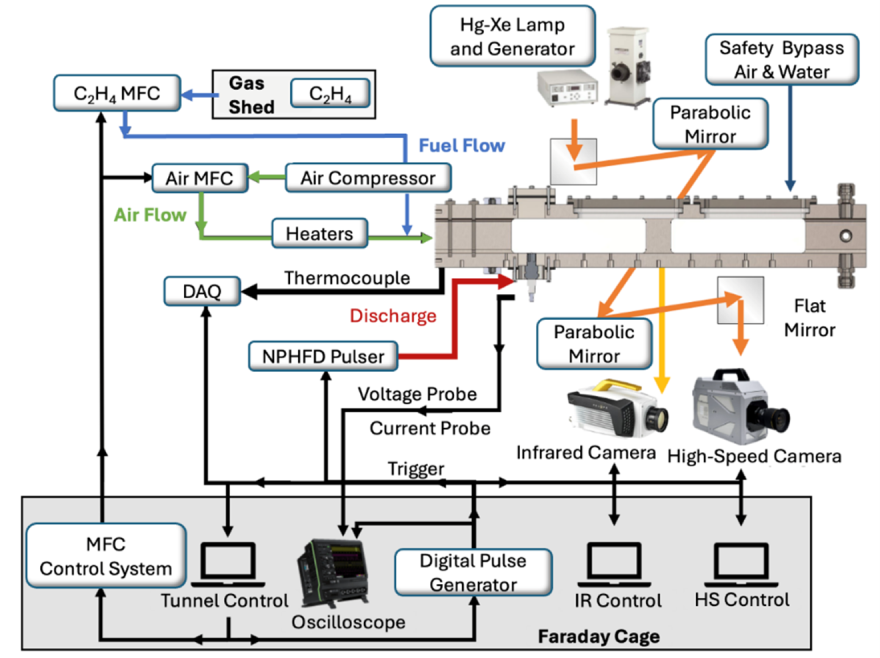
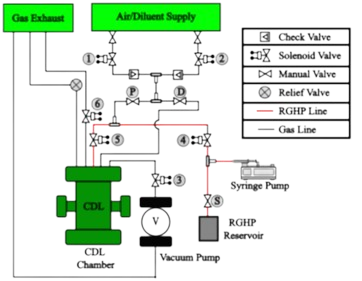
The experiment consisted of spraying RGHP from a nozzle situated vertically above the fuel sample within a stainless-steel chamber, with the gas and oxidizer flow remotely controlled by solenoid valves to regulate both the oxidizer delivery and the composition of the diluent gas, as shown in Figure 1. After each ignition, the chamber was purged with  and then depressurized to atmospheric conditions, allowing for a restart and the repetition of the experiment.

The Chamber has four sapphire window viewports, allowing optical access both in the infrared and visible wavelengths. The imaging setup for the work involved using three cameras placed adjacent to the three viewports with a powerful DC LED light placed adjacent to the remaining window. The imaging setup for the experiment is shown in the following figure.

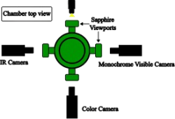
The infrared camera was the Telops FAST M3K and the monochrome visible imaging camera was the Photron SE-Z. Both these cameras provided optical access in the infrared and visible imaging ranges, respectively, and were set at an image acquisition rate of 2000 frames per second. The IR camera, in conjunction with an attached optical filter, could also detect species like water, CO2 and hydrocarbons from the ignition event. The third camera was a color camera (Phantom V310), which imaged at a rate of 200 frames per second and was utilized to provide contextual imaging of the droplet impingement and spray ignition event; the color images allowed for better imaging of the droplet impingement and combustion process.

Plasma Enhancement of Renewable Fuels
+

DBD Plasma Reactor:

  • A 62 cm3 quartz glass reactor with a stainless – steel inner electrode encased in a ceramic sheath (ground electrode) and a copper mesh outer electrode sewn to the outside of the reactor (high voltage electrode)
  • A dry scroll vacuum pump (Edwards 20i) is used to set the reactor pressure to 0.1 atm with constant gas flow

Discharge and Energy measurements:

  • Electrical discharges obtained with a custom-built nanosecond-pulsed high frequency discharge generator developed by FID GmbH (Maximum pulse repetition frequency: 200 kHz, maximum voltage: 20 kV, maximum discharge power: 500 W).
  • Pulse generator is triggered by a digital delay generator (Berkeley Nucleonics Corporation, Model 577).
  • High-voltage probe (Testec HVP 2739) and a current probe (Magnelab CT-E2.5-BNC) are installed in the system to measure the discharge voltage and the current. Probes are situated within 1 m of the discharge point due to the physical limitations of the system.
  • Oscilloscope (Teledyne Lecroy, Model HDO6104) records the discharge voltage and current waveforms. Discharge energy is computed from measured voltage and current with an in-house developed code. A voltage of 20 kV resulted in energy per pulse (Epp) of 9.6 ± 0.15 mJ

Diagnostics:

  • Gas chromatography with a thermal conductivity detector (GC-MS-TCD – Thermo Fisher Scientific Trace 1300 GC with ISQ 7000 single quadrupole mass-spectrometer) was also performed on the exhaust gas to quantify H2 production and O2 consumption.
  • A Fourier-transform infrared (FTIR) spectrometer (Thermo Fisher – Nicolet IS10) was used for FTIR spectroscopy on the exhaust gas to quantify ammonia concentration. A heated transfer line was connected to the output of the reactor, kept at above 100 ℃ using a temperature controller, and FTIR measurements were performed in a 100 mm path length heated gas cell (Pike stainless steel short-path gas cell).
  • An Andor spectrometer (SR-500i-B1-R) coupled with an intensified charged coupled device (ICCD) camera (Andor iStar CCD DH334T) was used to perform optical emission spectroscopy (OES). to quantify the rotational and the vibrational temperature of N2 species where the rotational temperature corresponds to the gas temperature of the plasma