


- Adi Green, Alexey Lisitskey, Avraham Barel, Eliran Levi, Gal Zohar, Guy Waldner, Idan Eisenberg, Kfir Reuven, Lilach Rafailov, Noam Brodi, Orel Laufer.
- Shlomo Shpund
- In the field of propulsion – Dr. Shimon Saraf, In the field of flight control – Roman Gendelman
General Overview
The main requirements for the platform are:
- Fully autonomous flight, including takeoff and landing
- At least 15 minutes of flight time
- Cruise at Mach 0.2÷0.4
- Reaching Mach 0.5
- Vertical maneuver acceleration up to positive 3g and negative 1g
- Landing speed in the range of 30÷40 m/s
- Round nose to accumulate a seeker in the future
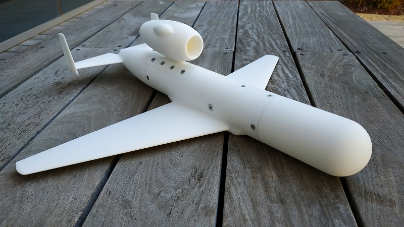
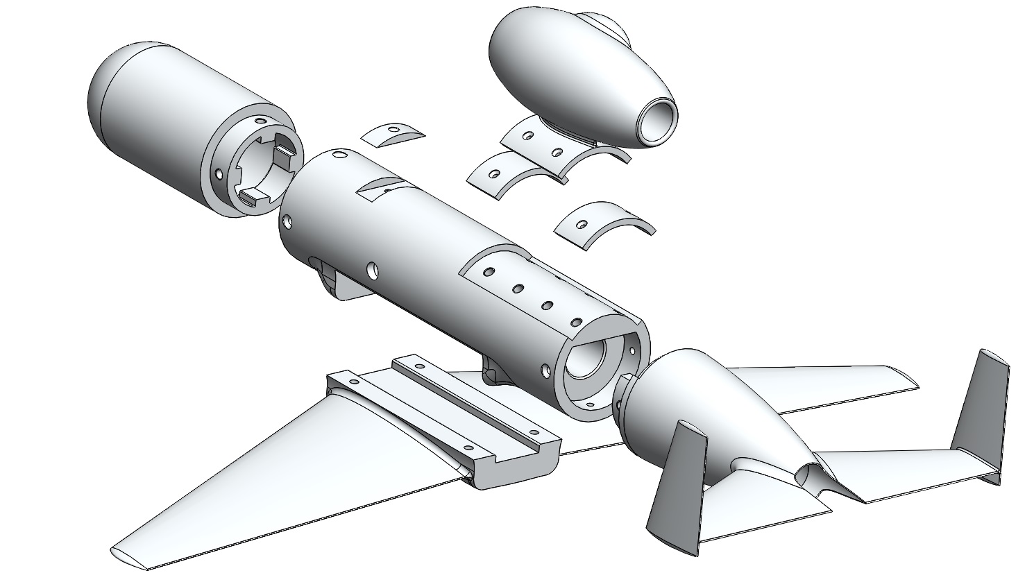
The integration of a jet engine onto an airborne platform is not trivial and has its unique design considerations in store. Some of the basic design considerations are: available space for an intake, considering the influence of the hot gases exiting the engine, using a proper fuel tank and fuel pump etc. Another consideration regarding the aircraft for example, is the usage of folding landing gear, instead of simple fixed ones to reduce drag and enable the vehicle to reach the required high speeds. After reviewing the different requirements and considerations, the final configuration of the UAV reached is a simple cylindrical fuselage with a round nose and a “boat tail” configuration. Fitted with a low mounted swept wing and an “H” tail to allow passage for the hot exhaust gases of the external top-mounted jet engine.
The aircraft’s fuselage is 170 millimeter in diameter. The fuselage length and the wing span are both 1360 millimeter in size.
The engine was chosen to be positioned externally to the fuselage for several reasons:
- An internally mounted engine requires designing of an integral intake to the fuselage, usually complex in geometry and structure.
- An internally mounted engine requires a considerable dedicated volume to accommodate the engine and the intake.
- An externally mounted engine allows for easy and fast access to maintenance and usual operation procedures before and after the flight.
After choosing an external mounting of the engine, the question that arises is where to position it. The options considered were below the fuselage or above it. The latter was chosen, mainly due to the risk of suction of objects from the ground when taking off or landing with a low mounted engine. Another reason for choosing a top mounted engine is that a low mounted one would reduce the ground clearance in takeoff and landing, or alternatively require using longer and heavier landing gear.
Also considered, is the risk of the hot jet exhaust hitting the fuselage, stabilizers or controls of the aircraft. For that reason, the tail of the aircraft was chosen to be in an “H” configuration, so that the hot jet will pass between the vertical stabilizers.
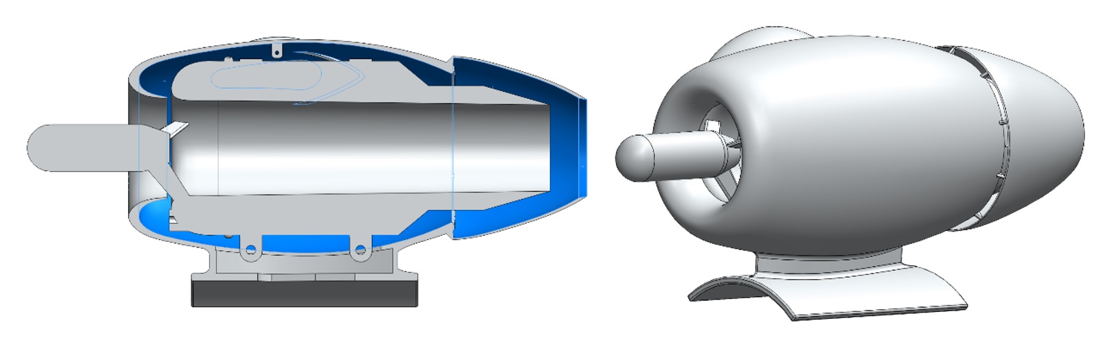
The externally mounted engine required also the design of an aerodynamic cowling that allows drag reduction, while protecting the wiring and fuel conduit to the engine. The cowling was designed with a vent opening that would help to reduce the temperature of the exhaust nozzle. Further design and validation of this cowling design will be done during the second year of the project.
A wind tunnel test was carried out to validate the configuration’s integral aerodynamic coefficients and the effect of the engine’s longitudinal position (along the fuselage) on the aerodynamic properties of the configuration. From the test’s results, the optimal position for the top mounted engine was chosen. The test also included examination of the engine’s pylon height.
The wing of the aircraft is low, tapered and swept back, featuring a conventional NACA0012 airfoil favored over other airfoils examined. The wing is low mounted to reduce the landing gear length, and to allow a structural beam to run through the fuselage without interfering substantially with other inner components meant to be fitted in the fuselage.
The required flight time is, as stated, 15 minutes. This requirement calls for an amount of fuel to be carried within the aircraft being a significant fragment of the whole vehicle take-off weight. When burned during flight, the center of gravity of the aircraft may change substantially which may hinder the stability of the aircraft. The chosen solution is to manufacture a customized flexible fuel tank that maintains its center of gravity in pre-defined limits, enabling an easier design of the aircraft’s static margin. The fuel tank’s specification was delivered to an external engineer.
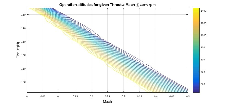
During this first year, extensive calculations and assessments were made to predict the aircraft’s performance. Among those are: an altitude and Mach dependent engine map delivering calculated engine performance as well as trim maps and detailed flight envelopes.
After the initial calculations, tests were made to validate both the aerodynamic design and the engine’s performance estimates.
A wind tunnel model was printed out of Nylon 12 in the scale of 1:2.5. The model was designed to be modular, allowing for example, test runs with only the fuselage and wing or with different positions of the engine. The design phase of the model included detailed load analysis, showing no need for reinforcements of the structure. For that reason, it is all made from plastic, apart from the metal bolts and bolt inserts connecting the different parts of the model.
The wind tunnel test was held in the subsonic wind tunnel in the Technion. The test results mostly showed good correlation to the predicted properties, apart from a difference in the parasitic drag coefficient, which was almost twice the estimated value. This caused the maximal estimated speed to reduce from 0.45 Mach to 0.35 Mach at sea level flight. Further findings from the experiment are detailed in the experiment’s and the full project’s reports.
The test was conducted under the supervision and guidance of associate professor Gil Iosilevskii.

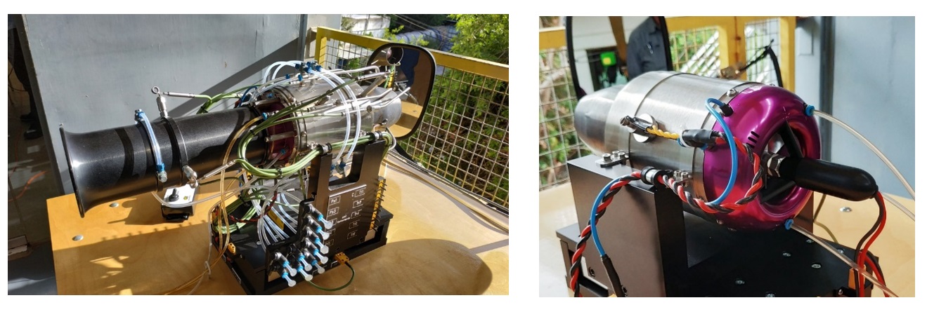
In addition to the wind tunnel test, engine tests were held in the propulsion lab. The engine tests included testing on both the engine meant to power the aircraft – the HP Pegasus, and an educational kit HP Olympus more powerful engine equipped with different measuring probes. In these tests, the involved team members studied the performance of the engines as well as how to operate them. Examination of the results showed excellent correlation to the estimations and good correlation to the manufacturers specification.
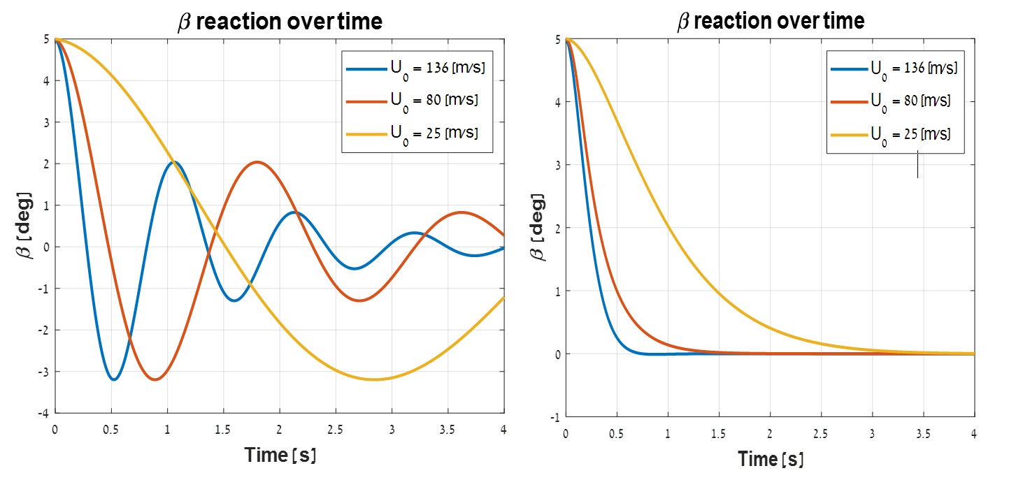
Another major aspect of the aircraft is its autonomous flight capability. Substantial progress in the design of flight controllers was made to allow this capability. The flight controllers were designed using simplified and approximated flight dynamics models, which were later tested upon a full dynamic model of the aircraft. The design concentrated on providing robust controllers, without hindering the response time of the overall system, in all flight planes. Further on, among other things, the controllers will allow an autonomous landing and takeoff.
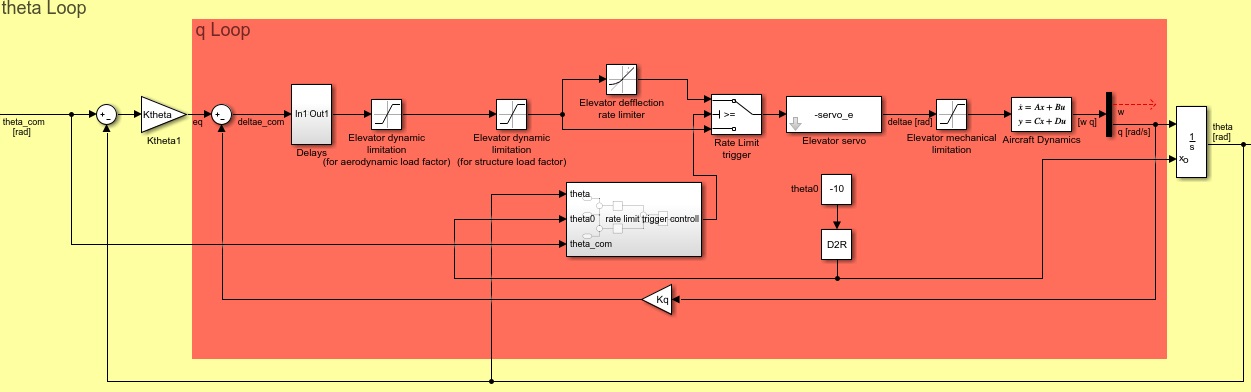
The designed control loops also helped choosing the elevator’s size for the aircraft. The initial control surface was too large, meaning that with only a minute change of tilt relative to trim, a high-g maneuver will be performed when at high speeds. The servo actuators have limited resolution accuracy and can’t reliably provide the fraction of a degree tilt required for such a control surface. For that reason, different elevator sizes were tested with the longitudinal control loops. By checking the control surface tilt required relative to trim for high speed maneuvers, and considering the accuracy of the actuators, the elevator size was chosen. As an example, the design of the lateral control loop is presented in fig. 8
A three degrees of freedom (motion in all three axes with no rotation) flight simulation was built to check the flight performance of the aircraft, in various flight conditions. This tool was validated by comparison to basic performance calculations made for the aircraft. In fig. 9 below a typical flight path that was checked is presented.

In the second year of the project, the next group of students will carry on to an advanced detailed design phase, in preparation for the third year of the project during which the aircraft will be manufactured and flown for the first time.
A link to the first year’s summary video:
https://youtu.be/sPwb-8LWG6U
