

DRIVESAT 2020
- Nikita Kazovski, Thomas Friedman, Alon Han, Mor Gilad, Dana Ben-Baruch, Carmel Polikman, Maayan Sigman, Areej Eweida
- Mr. Jacob Herscovitz
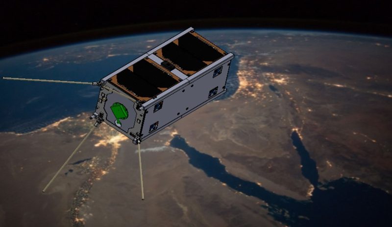
DriveSat is a student satellite project that aims to demonstrate two advanced CubeSat technologies: an electric propulsion system based on the inline-screw-feeding vacuum arc thruster (ISF-VAT) Fig 2, and a hard-disk drive momentum wheel (HDD-MW) Fig 3. In this second year of this project the team has made great progress towards the realization of the mission. Major strides were made in verifying compatibility of the experimental thruster and the on-board computer (OBC). Other team members focused on the mission profile and in orbit experiment design. The control team has created robust attitude determination and control algorithms for different flight stages. And the structural team has verified that the satellite will operate correctly under launch and orbit conditions.
In recent years, CubeSats are seeing a drastic increase in use, with more than 1200 launched as of 2019. For many nanosatellites, no propulsion technology exists within their extreme size and weight limitations. Currently these satellites have no control over their orbit and can’t correct for drift, perturbations, or orbit injection errors. Also, their mission life is severely limited by orbital decay. Drivesat is a technology demonstrator, its primary payload is an experimental thruster that is being developed by ASRI. Additionally, it has a new momentum wheel design that is based on an off the shelf hard drive. It offers the same functionality at a drastically lower price point.
DriveSat Propulsion
The inline-screw-feeding vacuum arc thruster (ISF-VAT), shown in Fig. 2, is a miniaturized plasma thruster under development at the Aerospace Plasma Laboratory (APL), Technion [2]. The ISF-VAT can offer a thrust level of up to 22 µN at a power of 2.6 W [3]. A propulsion module (PM) containing 2 ISF-VATs and a power processing unit was developed at APL. The PM has a mass of 200 g, a volume of 1/4 U, and requires power of 6.5 W. DriveSat will include 2 PMs and will utilize them to prove orbit control capabilities.
DriveSat Attitude Control
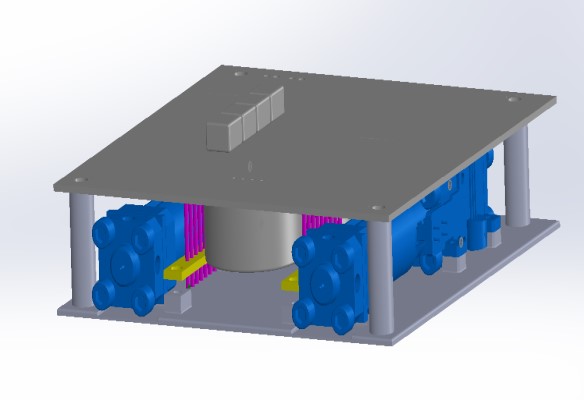
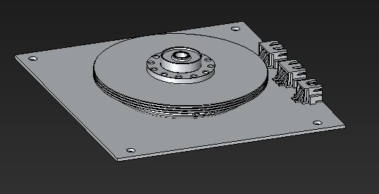
The secondary mission involves a novel approach to satellite momentum wheel implementation. The concept, proposed by the Asher Space Research Institute (ASRI), involves replacing the highly expensive dedicated momentum wheels offered by various space-technology firms with a modified computer hard-disk drive, forming a hard-disc-drive momentum wheel. This concept, once proven, can help significantly reduce the costs of many nanosatellite projects, thereby increasing their accessibility.
The HDD-MW will utilize the disc and motor from the hard-drive with minimal alterations and function exactly like a standard momentum wheel as part of the satellite’s attitude determination and control system (ADCS). DriveSat will use a single HDD-MW, along a single axis and a magnetorquer system for a 3-axis attitude control.
Integration experiment
The VAT generates strong magnetic fields when operating. These fields may interfere with other components of the satellite, particularly dangerous is the possible reboot of the OBC. Therefore, it is important to test this relationship on the ground. For this reason, an integration experiment was conducted. In this experiment we simulated space environment in a vacuum chamber Fig 4. While the OBC is communicating with the thruster and sending proof of life to the operator the thruster was activated and data was collected. At no point in the experiment did the OBC reboot eliminating this risk to the mission. The experiment is separated in to 4 parts.
- External power and control, no common ground.
- External power and control, shared ground.
- Internal power and control, shared ground.
- Internal power and control, floating (no ground)
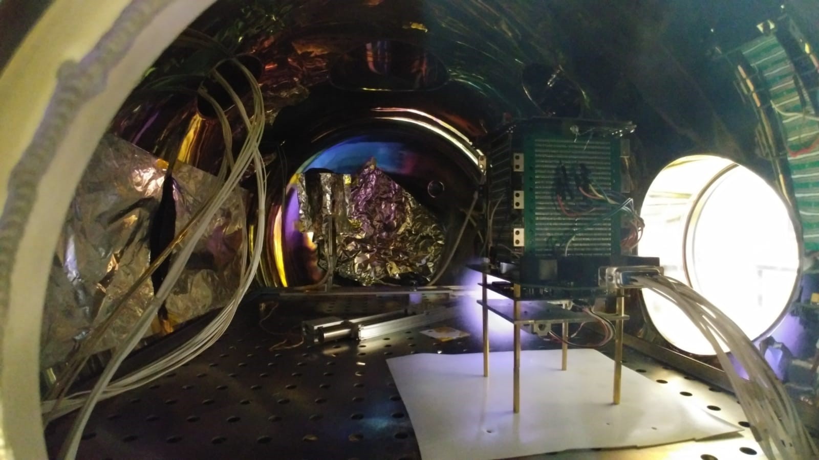
It was established that while the setup is electronically connected to the vacuum chamber there is considerable noise in the signals, however, when the system is “floating” there is nearly no noise. This would probably mean that the noise comes from the lab systems and not from the satellite itself. The experiment is deemed a success because the OBC continues to function properly in a simulated space environment.
Attitude control system
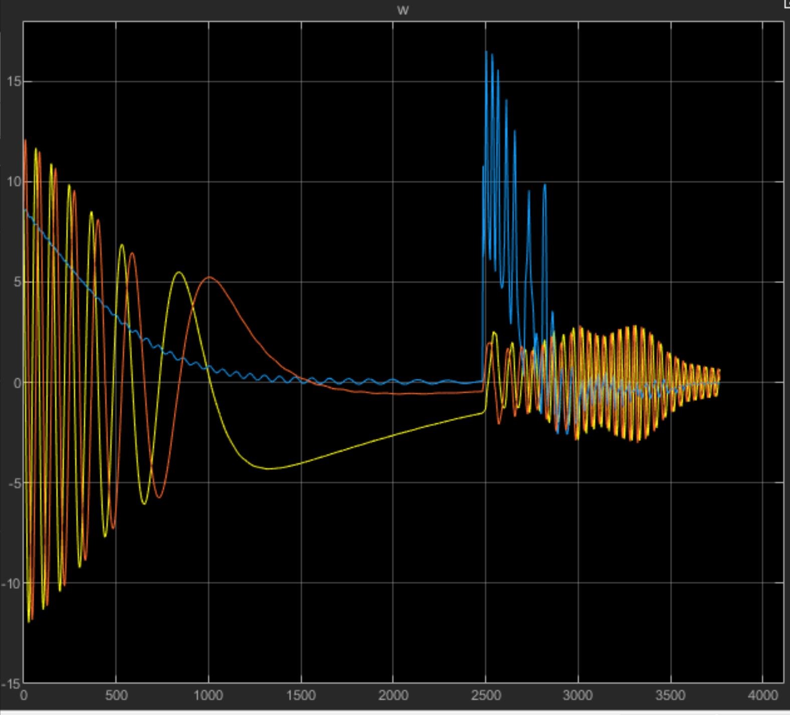
The team focused on creating control algorithms that can be directly transferred to flight hardware. the algorithms had to be comprehensive enough to accommodate all mission needs. The team has succeeded in creating and testing control modes for detumbling which is the first phase after separation from launch vehicle. In this mode the satellite must estimate spin rates in all axes and use only magnetorquers to reduce them to zero. Next is the sun cruise mode in which the satellite must maintain a specific orientation to maximize solar energy collection. The last two modes are for each payload test which means maintaining orientation so that engine thrust will be opposite the velocity vector. All modes were implemented with non-ideal sensors and actuators in mind. Control simulation results Fig 5.
Estimator
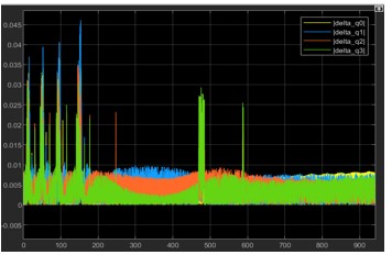
Part of the control team effort was to create a robust algorithm for the satellite to use as input into the attitude control algorithm. This attitude estimator must be fast enough to be useful in a real scenario, and accurate enough to allow for low errors in the final satellite state. The errors must be no more than: 0.1deg orientation error, 0.1deg/sec angular velocity, and have 0.05sec convergence time. The team used SVD-aided UKF algorithm to achieve this goal. Results Fig 6.
Structure
This team had to ensure that the structure will not resonate with the VEGA launch vehicle from liftoff to separation. And afterwards we made sure that every component will remain within its designed temperature margins for the duration of the mission. To accomplish this the team used ANSY WB to conduct finite element analysis on individual non-COTS components, as well as the entire satellite assembly. The team conducted static simulation of acceleration that the satellite will experience. The results showed very low stresses due to acceleration. Afterwards the team made more detailed simulation of resonant frequencies of components and of the structure. The data available was for the launch vehicle payload plate so the team had to simulate the satellite while it is inside the personal deployer (PPOD).
After modal analysis was complete the shock response could be simulated. The resulting shock will not exceed the yield strength of the material with safety factor of 3.
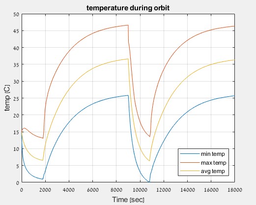
Next the team simulated the satellite temperature for 2 orbits when the internal heat transfer was simulated accurately, and heat flux was approximated from the earth, the sun, and background. The result was that no component will be outside of its allowed temperature range Fig 7.
Conclusion
The Drivesat second year team has made great progress in this project. Much work was outside the scope of this document. The project is far from completed and there is work to be done in the integration and communication aspects of the project. However, much work was completed, and most parts can pe purchased for continued ground testing. This was and will continue to be a great learning opportunity for students looking to try their hand in a difficult and interconnected design environment of such a complicated system. Commercially this technology has the promise to greatly expand the capabilities of nano satellites and to reduce mission cost.
