Thrust-X Aerobatic Airplane
- Eliezer Azoulai, Ben Mutzary, Dmitry Shapiro, Noam Gazit and Maytav Einhorn
- Mr. Shemer Slav
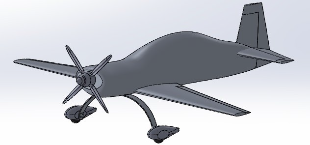
The following project is about the characterization and design of an aerobatic aircraft meant to participate in aerobatic displays. This project was done under the supervision of the group mentor, Mr. Shemer Slav, and with the co-operation of Professor Chaim Abramovitch, Dr. Mickey Golan, ARAN R&D company and Mr. Ludger Dülmer from the company EXTRA Flugzeugproduktions- und Vertriebs- GmbH. Group. The team leader is Ms. Maytav Einhorn.
The project presents a plane specifically designed for performing aerobatic exercise. The design requirements were dictated by flight conditions during the aerobatic exercise. These exercises are performed at aerobatic conventions such as CIVA and are done one after the other in front of a live audience. This type or plane is unique due to the fact that it must perform under extreme circumstances such as: large sliding angle, large forces in proportion to mass (high G’s) and fast rolling rates. All of these conditions were accounted for in the design process.
The following report specifies the design process of the plane Thrust-X including the analysis theory (in the fields of aerodynamics, flight mechanics and structural design), experiments (building the model, conducting the wind tunnel experiment and the analysis) and programming a simulation.
 Figure 1 – Thrust-X ; Isometric view
The following report begins with the requirements dictated by the client. These requirements dictate the airspace in which the exercises will take place and other design requirements. The report displays the design of the wings tail and body of the plane. Also, it displays the simulation of the plane and the explanations and discussion about the results.
The wind tunnel model was 3D printed by ARAN R&D company and was installed into the subsonic wind tunnel at the Technion’s aerospace faculty. The problems with the installation process and the solution are displayed and discussed. The simulation of the model is displayed along with an explanation and a discussion about the results. The experiment was conducted in a polar and tangential manner and is compared to the simulation results of the Thrust-X.
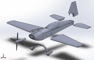 Figure 2 – Wind tunnel model ; Exploded view
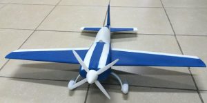 Figure 3 – The Wind tunnel model
Due to known structural strength problems in such planes, an idea arose was to measure these forces in the wind tunnel experiment. For the reason measurements of the torque created during large sliding angles were conducted.
Estimations of the plane’s capabilities were displayed including: aerodynamic forces, fuel calculations, plane sketches and explanations. Since they are essential to check that the plane is able to take-off according to FAA rules, lift-off capabilities were calculated. It was proved that the airplane is capable of taking off according to the demands. Calculations of the take-off distance were performed as well. Finally, it was proved that the airplane meets the requirements.
An in-depth analysis of the tail is displayed alongside graphs and calculations. Tail configurations of 2 and 4 beams were validated and weights were estimated. Finally, the chosen solution for the tail was: four bars of 0.05 m. An ANSYS model was created in order to validate the model and proved that the expected displacements take place where the stress is the largest.
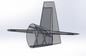 Figure 4 – Application of the tail’s truss
A six-degrees-of-freedom (6DOF) simulation of straight flight and a loop were conducted with the help of a code on MATLAB. This simulation is displayed alongside relevant explanations, graphs and formulas.
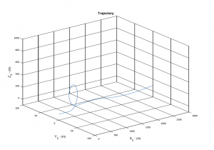 Figure 5 – 6DOF simulation; Vertical loop maneuver
Finally, a Schrenck approximation and a theoretical mathematic model were displayed alongside graphs, equations and an explanation.


