

DRIVESAT 2021
- Michal Pushkov, Tom Nezer, Lisa Bernstein, Elinor Borenstein, Opal Hachmon, Aya Rudek
- Jacob Herscovitz
Introduction
The DriveSat is a 2U Cubesat satellite which is developed by fourth-year students and led by the Technion and Asher Space Research Institute.
The DriveSat will perform the following missions:
- Test the newly developed ASRI-APL technology of ISF-VAT Electric Propulsion in a space environment and estimate its space performance.
- Demonstrate orbit control of a CubeSat using ISF-VAT.
- Demonstrate the use of a regular computer HDD as an attitude RW actuator, in the space environment.
Experiments
To achieve the mission’s goals, two experiments will be conducted in space:
- Orbit control –change of DriveSat altitude by operating the ISF-VAT thrusters. A typical maneuver will fire the thrusters 4 pluses per revolution in 13 revs.
- Thrust measurement by Reaction Wheel applying angular counter-moment and balancing the VAT-ISF thrust level.
The measured parameters (the orbit by GPS and the torque of HDD-RW) will be downloaded to the ASRI ground station for processing and estimation of the two payloads’ performance.
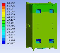
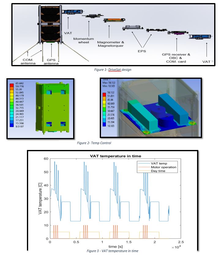
Structure
The main goal of the current work was to finish and verify the DriveSat design. This year we have chosen a PPOD to launch the DriveSat, wrote integration procedures, and defined the mass breakdown. To verify the DriveSat design, structural and thermal analyses were conducted
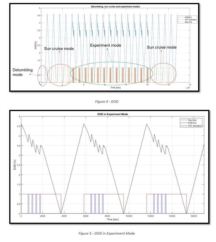
Power Simulation
The main goal of the simulation was to verify the satellite power design and mission performance, by checking the electrical system’s ability to supply power to all the satellite’s components during different modes in a safe mode. The main criteria were to assure the battery life won’t be shortened drastically during the mission. The main requirement was the depth of discharge (DOD) will not increase beyond 15%.
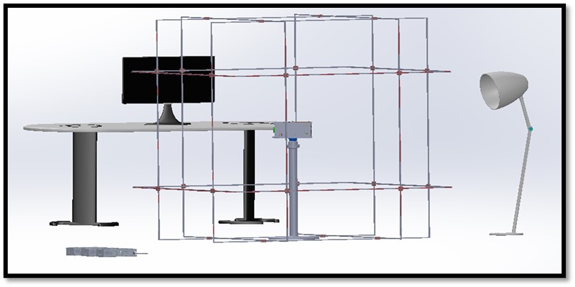
Testing Lab
A testing lab was defined and preliminary designed, consisting of three test systems: Magnetic and Sun simulators which will simulate the space magnetic field and solar radiation accordingly during the mission, and an Air Bearing which will allow DriveSat free (almost) frictionless movement in three degrees of freedom. All three test systems will allow the generation of orbit conditions environment to test and confirm the correctness of attitude control algorithms and test the sensors and actuators subsystems (magnetorquers and magnetometers).
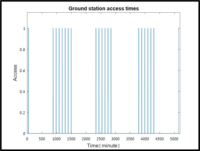
Ground station
To diagnose the satellite health and the status of DriveSat experiments, it is essential to download telemetry to the ground station in each possible access. The required telemetry was selected, a sampling rate was chosen for each mode separately through a careful trade-off balance between collection storage and downlink time. For example, it was found that after 5 consecutive accesses to the ground station, there is one long-time delay to the next access. This issue has been addressed and is fixed by special communication functions and algorithms that will be responsible for handling this situation.
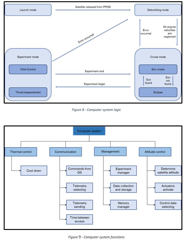
Computer system
All the activities that the satellite will complete while it is in space are managed by the software. The satellite switches between different modes (sun cruise, eclipse, etc.) according to the satellite states scheme that has been done. Also, this semester we have defined the basis of the functions for the software, communication functions, control functions and thermal control functions.
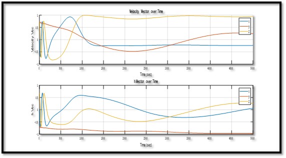
Control Simulation
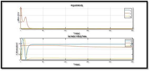
DriveSat’s control system is built to operate in 3 modes: Detumbling (stabilizing the satellite after launch), Sun Cruise (directing the satellite in the optimal attitude for maximum sun energy), and Experiment mode (pointing and keeping DriveSat in the necessary direction to fire the thrusters in each experiment).
Detumbling – In this mode we stabilize the satellite after the launch. This is done with control law B-Dot which uses MT Torque.
Sun Cruise – In the first step, we will stabilize the satellite and have a large momentum in the y axis. This is done by applying an external torque on the body in the y axis and applying an internal torque in the Y-axis on with the RW. In the second step, we will rotate the satellite to face the sun by calculating the angle between the satellite and the sun using the sun sensor. After achieving the desired orientation, the control system will maintain it until the command for an experiment.
Experiment – Experiment mode points the thrust in the direction of the velocity vector. To increase the potential experiment time, after achieving the desired orientation the control system will maintain it until the end of the experiment.