SAMSON – Wing-in-Ground-Effect Transport Aircraft
- B. Gaiduk, E. Yujelevski, O. Markovich, A. Prosvetov, D. Kuitkov, A. Klebanov, I. Kaprovsky, A. Rosich, R. Reitbort, E. Shavelzon, J. Shamenzon
- Dror Artzi

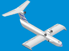
Samson, named after the biblical hero, is a heavy transport wing-in-ground-effect aircraft designed by a team of students. This project is yet another attempt to take advantage of cruising in close proximity to the ground. Since early times aviators have been aware that the presence of an impenetrable surface below a lifting wing influences its aerodynamic properties, the so-called ground effect. Studies of the ground effect show that it leads to increase in lift coefficient and decrease in induced drag, thereby improving wing efficiency. At the same time, the ground effect changes chordwise lift distribution effecting the pitch moment. Every flying vehicle is subject to the ground effect during takeoff and landing, a fact that has to be considered in the design process. However, attempts are being made to design vehicles that make use of the ground effect to their benefit. Such vehicles are usually referred to as WIG (wing-in-ground effect) or WISE (wing-in-surface effect) craft. WIG craft have many advantages, from both aeronautical and marine engineers standpoints such as high efficiency during cruise, no need to pressurize the cabin, small turn radius (especially in comparison to hovercraft) and more. On the other hand many disadvantages have prevented the wide use of WIGs.
The System
The final configuration of the WIG is a combination of two turbo-fan and three turbo-prop engines, with the turbo-fan engines only being activated during take-off. This engines configuration was derived from low fuel consumption and high flight range requirements. This configuration, which was chosen out of three, was the best because it gives the longest range for the WiG. The turbo-fan engines (HK-32) were locataed in such a manner that the diffusers would be found inside the fuselage above the cockpit (so that the aircraft flow facing area and shape drag would decrease, and the engines would be protected from water spray) and the nozzles would direct the engines jets to the lower wing surface generating an air cushion. As the project objective definition was cargo aircraft design, fuselage configuration was dictated mainly by payload requirements. Maximal payload (in 60 ton fuel take-off configuration) was defined as 120 ton in standard aviation containers of two types: LD3 and ALP containers.
Links:


